ViaPPS (Pavement Profile Scanner)
| Company | ViaTech AS |
|---|
Images

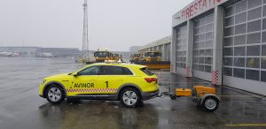
ViaPPS is inhouse technology developed by ViaTech AS, Norway (www.viatech.no) The main application of ViaPPS is for pavement (highway / airport) maintenance and safety. ViaPPS has multiple sensors which capture various parameters like cracking, rutting, ravelling, bleeding etc which defines the surface distress and entire pavement maintenance schedule can be planned based on this data. Using this equipment, any sort of distress can be captured at initial levels and pavement condition index (PCI) can be plotted. These studies are done on regular interval to check the condition of all the components of airstrip / runways. The best part of using this system is all the data’s can be processed automatically through the desktop application and within hours of survey, PCI can be calculated. This ensures that conditioning survey for the airport can be done in very short time and that too in an automated process.
Norwegian road authority is using this system since last 15 years for maintaining their highway. Considering the increasing traffic in aviation sector, preventive maintenance of all pavements (specifically runway and taxiway) is very important as any unplanned maintenance schedule can hamper air traffic in a big way and cost of any accidents on an airport is very huge. Considering this, most of the countries have mandated pavement scanning and friction measurement mandatory at the airports where studies are carried out at stipulated interval.
1. ViaPPS (Pavement scanner)
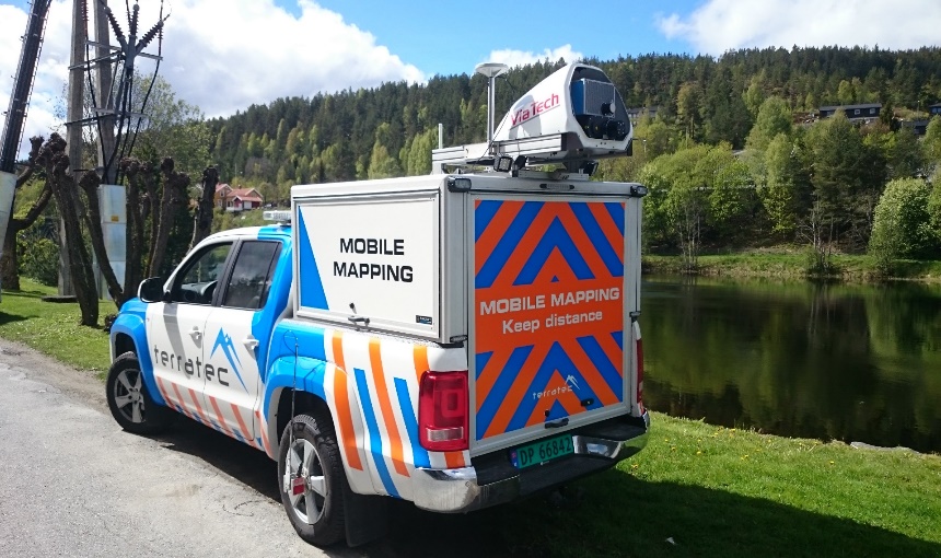
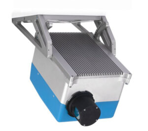
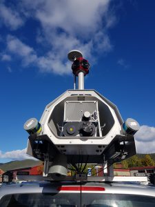
ViaPPS system is based on a high-resolution 3D point cloud of the road surface and the surroundings. A 360 degrees Laser scanner and an advanced positioning platform is used to generate a high-resolution 3D point cloud (1 million points per sec). The point cloud is used for automatic analysis aimed at evaluation of the conditions for the pavement and side area. The system is capable to operate in normal traffic speed.
1.1 Key Specifications of Scanner
- Sampling rate: 200 profiles /sec
- Measurement speed: 10-100km / h
- Measuring range: minimum 100m
- Horizontal resolution: 1100 points / profiles – 4m
- 360 degrees resolution: 5000 points/profile
- Accuracy of reading (vertical rangefinder): 0,5mm based on the distance 2-5 meter.
- The ability to measure in day or night-time.
- Laser class 1 (Eye safe)
- High performance position and orientation system
- The laser beam is a phase based.
The measurement is carried out at a vehicle at a 5 km / hour – 100 km/hour, which (at a frequency of 200 Hz) allows to capture profiles with 0.007-0.14 m intervals. The survey is carried out in air temperatures 0 – 50°C. (The surface has to be completely dry to guarantee the highest possible accuracy).
1.2 Essential requirements for the single point laser measurement system:
To measure the MPD (Mean Profile Depth) and IRI (International Roughness Index) the following requirements are fulfilled.
- The laser is mounted in the front of the vehicle- left /right / both wheel path.
- The laser is measured in the wheel path.
- Sampling rate: More than 32 kHz
- Measurement resolution is 0.045 mm or better.
- Operating temperature 0° to 50° C
- Ability to measure in day or night-time.
2. Registration system of the road corridor
2.1 Image cameras
The system is equipped with 1 front camera to record images of the road corridor: taking an image every 10 m. The registration of colour images provides a resolution of at least 2500×2000 pixels. The quality of the images allows identification of all normally visible elements of the road lane.
2.2 Time synchronization system
The vehicle is equipped with a time synchronization system on all devices used for measurements. All data events from all sensors is time-synchronized with the accuracy of 0.001s.
2.3 Distance measuring system
The vehicle is equipped with a distance measuring system based on incremental sensor installed on the wheel of the vehicle. Sensor resolution is 900 pulses per wheel rotation. The system can perform a precise master calibration. It is possible to carry out calibration procedure in the field without the need of using special tools. Distance measurement is synchronized with the data from the GPS and road network reference system.
2.4 Software for recording images
The control of the system for recording images is possible from the monitor available in the vehicle. The role of the operator is limited only to handle START / STOP buttons without the need for additional configuration during recording sessions. The user interface presents information about the statuses of the individual subsystems. In case of an error, proper information is displayed.
2.5 Image processing software
Tools to produce the combined material is provided to the user with problem free and fully repeatable process of processing of the source material in relation to the location of images on the road network. The user can determine the beginning and end of the measurement road section. The image viewer is a component of the delivered system. GPS coordinates included in meta data of JPG files.
3. The enhanced PC unit for calculation of registered files
3.1 The computer unit (PC) – office analysis of data
Included in the system is a PC with specialized software. The PC is used for automatic data analysis. The unit, in standalone housing, with the minimum configuration:
The Computer Unit
- 8-core I7-9700K CPU with 1151 socket
- Z390 Intel Chipset Motherboard
- 32GB RAM
- 4 TB Storage + 500 GB SSD System Disk
- 4-port Gigabit Ethernet Server Controller
- Ruggedized 400W power supply
- Ruggedized Cabinet
- 17” LCD IPS panel
- Mouse/rollerball and keyboard
3.2 Data analysis (automatic detection)
Software for data analysis enables automatic detection for the following parameters of asphalt / concrete pavement road lane
- Longitudinal and transversal profile
- Rut depth, rut area and rut area volume
- Crossfall & curve radius
- Longitudinal deflection and bumps
- IRI (International Roughness index)
- MPD (Mean Profile Depth)
- Width of the lane
- Crack parameters (Crack level, Crack area level, position)
- Vertical height to bridges/crossings, tunnel heights
Relative differences in texture (Homogeneity) of the width of the lane.
3.3 Software
Desktop Application
The main purpose of the desktop application is to generate text reports in csv format and to perform analysis of the road surface.
3.4 Image viewer
This facilitates viewing of images captured from different cameras and point cloud. The viewer has the following features:
- No license limitations
- Display a list of road sections available in the database
- Presentation of images with laser scanner association
- Display information about local mileage of the road section and global mileage of the road
- Possibility of making measurements in images.
- Possibility to read out geographical coordinates in any selected coordinate system
4. The navigation system and GPS
4.1 The positioning and navigation system (POS)
The positioning and navigation system is compact, fully integrated, turnkey position and orientation system, utilizing integrated inertial technology to generate stable, reliable, and repeatable positioning solutions for land-based vehicle applications.
Designed to operate under the most difficult GPS conditions found in urban and suburban environments, POS enables accurate positioning for road geometry, pavement inspection, GIS database and asset management, road surveying, and vehicle dynamics.
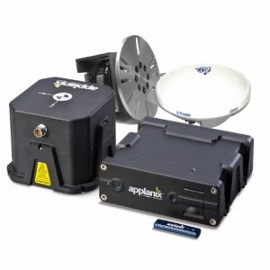
The POS system components:
- IMU: Inertial Measurement Unit generates a true representation of vehicle motion in all three axes, producing continuous, accurate position and orientation information
- PCS: POS Computer System which enables raw GPS data from as few as one satellite, to be processed directly into the system. It computes accurate positional information in areas of intermittent, or no GPS reception
- DMI: Distance Measurement Indicator computes wheel rotation information to aid vehicle positioning
- GPS Receivers: Embedded GPS receivers provides heading aiding to supplement the inertial data
- GPS Antennas: Two GPS antennas generate raw observables data.
The IMU is mounted within 30 cm of the scanner and on the same metal plate.
The IMU and Scanner is protected against rain and dust with a hard cover.
4.2 GPS System
The vehicle is equipped with GPS positioning system 200Hz to record the geographical coordinates of the vehicle with an accuracy of <0,35 m with available GPS signal in real time. After possible post processing the accuracy is <0,03 m.
Basic features:
- Coordinate measurement 200 HZ
- Accuracy of measurement: less than 0.35m
- The receipt of correction signals EGNOS, WAAS and OMNISTAR
- 2 x RS232 output for communication with a PC (NMEA output)
- Input and output RTCM
4.3 Ladybug camera
Along with the system, LadyBug5 camera from Point Grey is provided for taking 360 degrees photographs of the pavement and corridor.
The camera is mounted on a level alarm controlled by an actuator. The operator can control the camera position by a switch inside the vehicle. The images to be exported to panorama jpg image files.
5. Hardware documentation
For each system element the hardware documentation is provided in English.
6. Training in use of measuring apparatus and software processing the results
Upon delivery of the measuring system, training is provided at the pre-decided location. At least 5 employees so that each of them will be able to independently use the device and software processing measurement data.
7. Warranty on components of the measuring apparatus
Warranty for 1 years on components of the measuring apparatus is provided.
8. After-sales service, software updates and control calibration of the measurement system
ViaTech ’s warranty conditions ensure ongoing technical support (for hardware and software), software updates and an annual control calibration of the measurement system for 12 months.
9. Van
ViaTech will install the system in a van size like a WV Transporter, Caddy, Mercedes Vito, XUV 500, Mahindra Scorpio etc.
Cruise control, AC and automatic transmission are required.
10. Standards
ViaPPS follows the following standards
- ASTM E950 E965 E1703 D5340
- AASHTO PP69 PP70 PP86
- CEN EN 60825
- EN 13036
- ISO 13473
- PIARC 2008R14
1 ViaPPS (Pavement scanner)
ViaPPS system is based on a high-resolution 3D point cloud of the road surface and the surroundings. A 360 degrees Laser scanner and an advanced positioning platform is used to generate a high-resolution 3D point cloud (upto 2.2 million points per sec). The point cloud is used for automatic analysis aimed at evaluation of the conditions for the pavement and side area. The system is capable to operate in normal traffic speed.
1.1 Key Specifications of Scanner
- Sampling rate: 267 profiles /sec
- Measurement speed: 10-100km / h
- Measuring range: minimum 180m
- Horizontal resolution: 2060 points / profiles – 4m
- 360 degrees resolution: 8240 points/profile
- Accuracy of reading (vertical rangefinder): 0,2mm based on the distance 2-5 meter
- The ability to measure in day or night-time
- Laser class 1 (Eye safe)
- High performance position and orientation system
- The laser beam is a phase based
The measurement is carried out at a vehicle at a 5 km / hour – 100 km/hour, which (at a frequency of 200 Hz) allows to capture profiles with 0.007-0.14 m intervals. The survey is carried out in air temperatures 0 – 50°C. (The surface has to be completely dry to guarantee the highest possible accuracy).
1.2 Essential requirements for the single point laser measurement system:
To measure the MPD (Mean Profile Depth) and IRI (International Roughness Index) the following requirements are fulfilled
- The laser is mounted in the front of the vehicle- left /right / both wheel path
- The laser is measured in the wheel path
- Sampling rate: More than 32 kHz
- Measurement resolution is 0.045 mm or better
- Operating temperature 0° to 50° C
- Ability to measure in day or night-time.
2. Registration system of the road corridor
2.1 Image cameras
The system is equipped with 1 front camera to record images of the road corridor: taking an image every 10 m. The registration of colour images provides a resolution of at least 2500×2000 pixels. The quality of the images allows identification of all normally visible elements of the road lane. For panoramic images (360 degrees) Ladybug 6 camera is provided with (12 x 6) 72 Megapixel.
2.2 Time synchronization system
The vehicle is equipped with a time synchronization system on all devices used for measurements. All data events from all sensors is time-synchronized with the accuracy of 0.001s.
2.3 Distance measuring system
The vehicle is equipped with a distance measuring system based on incremental sensor installed on the wheel of the vehicle. Sensor resolution is 900 pulses per wheel rotation. The system can perform a precise master calibration. It is possible to carry out calibration procedure in the field without the need of using special tools. Distance measurement is synchronized with the data from the GPS and road network reference system.
2.4 Software for recording images
The control of the system for recording images is possible from the monitor available in the vehicle. The role of the operator is limited only to handle START / STOP buttons without the need for additional configuration during recording sessions. The user interface presents information about the statuses of the individual subsystems. In case of an error, proper information is displayed.
2.5 Image processing software
Tools to produce the combined material is provided to the user with problem free and fully repeatable process of processing of the source material in relation to the location of images on the road network. The user can determine the beginning and end of the measurement road section. The image viewer is a component of the delivered system. GPS coordinates included in meta data of JPG files.
3. The enhanced PC unit for calculation of registered files
3.1 The computer unit (PC) – office analysis of data
Included in the system is a PC with specialized software. The PC is used for automatic data analysis. The unit, in standalone housing, with the minimum configuration:
The Computer Unit (minimum configuration- latest will be supplied)
- 8-core I7-9700K CPU with 1151 socket
- Z390 Intel Chipset Motherboard
- 32GB RAM
- 4 TB Storage + 500 GB SSD System Disk
- 4-port Gigabit Ethernet Server Controller
- Ruggedized 400W power supply
- Ruggedized Cabinet
- 17” LCD IPS panel
- Mouse/rollerball and keyboard
3.2 Data analysis (automatic detection)
Software for data analysis enables automatic detection for the following parameters of asphalt / concrete pavement road lane
- Longitudinal and transversal profile
- Rut depth, rut area and rut area volume
- Crossfall & curve radius
- Longitudinal deflection and bumps
- IRI (International Roughness index)
- MPD (Mean Profile Depth)
- Width of the lane
- Crack parameters (Crack level, Crack area level, position, classification)
- Potholes (size, width, depth, length, classification)
- Vertical height to bridges/crossings, tunnel heights
Relative differences in texture (Homogeneity) of the width of the lane.
3.3 Software
Desktop Application
The main purpose of the desktop application is to generate text reports in csv format and to perform analysis of the road surface.
3.4 Image viewer
This facilitates viewing of images captured from different cameras and point cloud. The viewer has the following features:
- No license limitations
- Display a list of road sections available in the database
- Presentation of images with laser scanner association
- Display information about local mileage of the road section and global mileage of the road
- Possibility of making measurements in images.
- Possibility to read out geographical coordinates in any selected coordinate system
4. The navigation system and GPS
4.1 The positioning and navigation system (POS)
The positioning and navigation system is compact, fully integrated, turnkey position and orientation system, utilizing integrated inertial technology to generate stable, reliable, and repeatable positioning solutions for land-based vehicle applications.
Designed to operate under the most difficult GPS conditions found in urban and suburban environments, POS enables accurate positioning for road geometry, pavement inspection, GIS database and asset management, road surveying, and vehicle dynamics.
The POS system components:
- IMU: Inertial Measurement Unit generates a true representation of vehicle motion in all three axes, producing continuous, accurate position and orientation information
- PCS: POS Computer System which enables raw GPS data from as few as one satellite, to be processed directly into the system. It computes accurate positional information in areas of intermittent, or no GPS reception
- DMI: Distance Measurement Indicator computes wheel rotation information to aid vehicle positioning
- GPS Receivers: Embedded GPS receivers provides heading aiding to supplement the inertial data
- GPS Antennas: Two GPS antennas generate raw observables data.
The IMU is mounted within 30 cm of the scanner and on the same metal plate.
The IMU and Scanner is protected against rain and dust with a hard cover.
4.2 GPS System
The vehicle is equipped with GPS positioning system 200Hz to record the geographical coordinates of the vehicle with an accuracy of <0,35 m with available GPS signal in real time. After possible post processing the accuracy is <0,03 m.
Basic features:
- Coordinate measurement 200 HZ
- Accuracy of measurement: less than 0.35m
- The receipt of correction signals EGNOS, WAAS and OMNISTAR
- 2 x RS232 output for communication with a PC (NMEA output)
- Input and output RTCM
4.3 Ladybug camera
Along with the system, LadyBug6 camera from Point Grey is provided for taking 360 degrees photographs of the pavement and corridor.
The camera is mounted on a level alarm controlled by an actuator. The operator can control the camera position by a switch inside the vehicle. The images to be exported to panorama jpg image files.
5. Hardware documentation
For each system element the hardware documentation is provided in English.
6. Training in use of measuring apparatus and software processing the results
Upon delivery of the measuring system, training is provided at the pre-decided location. At least 5 employees so that each of them will be able to independently use the device and software processing measurement data.
7. Warranty on components of the measuring apparatus
Warranty for 1 years on components of the measuring apparatus is provided.
8. After-sales service, software updates and control calibration of the measurement system
ViaTech ’s warranty conditions ensure ongoing technical support (for hardware and software), software updates and an annual control calibration of the measurement system for 12 months.
9. Van
ViaTech will install the system in a van size like a WV Transporter, Caddy, Mercedes Vito, XUV 500, Mahindra Scorpio etc.
Cruise control, AC and automatic transmission are required.
10. Standards
ViaPPS follows the following standards
ASTM E950 E965 E1703 D5340
AASHTO PP69 PP70 PP86
CEN EN 60825
EN 13036
ISO 13473
PIARC 2008R14
Other Products From ViaTech AS