Emergency Handset System
| Company | Copperchase |
|---|

Images
The Copperchase Emergency Handset System (EHS) can be used in airports of all sizes, from small regional airports to the larger international airports. As a cost-effective system solution, the EHS provides complete ATC communications in the event of a failure of the main VCCS.
The system is of a modular design and is constructed in blocks of eight consoles. The EHS is an independent system and does not support inter-console communication, allowing larger systems to be easily supported by simply installing more EHS 408 modules. Based on this ethos, there is no upper limit to the number of consoles that can be installed.
Each console can provide single or multiple connections to:
Up to four shared telephones (Direct Line)
Four radios (Tx/Rx), which can be a discrete radio channel per console paired between two consoles.
The four telephones can be configured as a shared resource between four consoles on a “first come, first served” basis or discretely allocated to an individual console (one per console).
Likewise, the radio channels can be allocated as two radios per two consoles (paired), i.e. Channel 1 on Console 1 will appear as Channel 2 on Console 2, and vice versa. This serves for applications where the VCR may be manned by two controllers during the day and only one at night, who may need to operate both R/T channels simultaneously. Alternatively, the radio channels can also be discretely allocated to one console (one per console).
The system consists of a base control unit with remote consoles connected via standard cat5 cable and external adaptor cards for conversion from the base control unit out to the external radio and telephony connections. The EHS retains all audio in an analogue format to ensure ease of installation and commissioning and also to reduce fault issues applicable to UK CAA SRG requirements.
All call-status and lamp/switch field information is passed between consoles and console to the base control unit using a high-speed 2W data communications method (CANbus). This allows all consoles to pass information directly between units regardless of the base system status, thus increasing system integrity and reducing failures due to single-point failure.
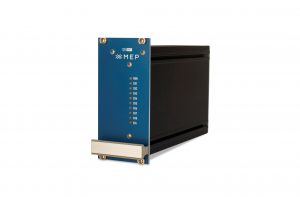
Base Control Unit
A standard four console system with four radios and four telephones is supplied in two 3U Euro-racks. One sub-rack contains all console interfaces (CIFs) and radio interfaces; the other contains the telephone interfaces.
Radio interfaces can be configured to cater for the following:
Separate auto signalling lines
- 600 ohms audio
- Dry relay aircraft call and PTT
- -48VDC aircraft call and PTT
- Combinations of the above
Audio with phantom signalling
- Audio with phantom signaling
- 600 ohms audio
- Dry relay Aircraft call and PTT
- -48VDC aircraft call and PTT
- Cobminations of the above
Operator Positions
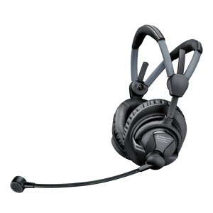
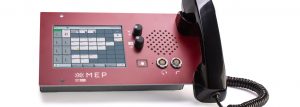
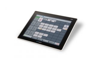
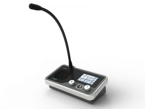
Each console is connected directly to the base control unit via a standard 4pr Cat 5 cable. This allows a pair for all data traffic for routing and lamp/switching operation, two pairs for the headset (left and right ears) and one pair for the microphone.
The console can be either a 19” rack-style construction, allowing fitment in to a standard 19” desk, or a modular P3 construction.
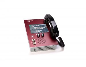
Each console has the capability to communicate with up to two radios and four telephones. The system remains in a dormant state with only the status LED lit until the Emergency Handset is removed from its cradle. When this happens the default configuration will appear at the console:
- Ch 1 Active
- Ch 2 Monitor
- All buttons backlit
Separate volume controls are available for radio and telephone so that a level and balance suitable to the operator can be quickly and easily achieved.
Power Supplies
All consoles and interface equipment is designed to be powered from -48VDC and 230VAC, 120VAC can also be accommodated. The standard system is supplied with all AC / DC supplies and a battery backup system designed to run for 2 hours should there be failure of mains power.
Alternatively, the system can be powered from two mains sources or two -48VDC sources.
Other Products From Copperchase

ATIS and D-ATIS - Automatic Terminal Information Service

Digital Voice Communications System
Line Communications Equipment
Four Radio Control Panel