Air Traffic Control Alarm Monitoring System
| Company | Copperchase |
|---|
Images
Flexible Alarm Monitoring
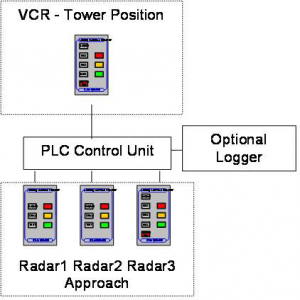
The Copperchase Alarms Monitoring System for airfield ground-based ATC systems and navigational aids offers state-of-the-art touch-screen and Programmable Logic Controller (PLC) packages tailored to the individual needs of the airfield operation. The system can be economically modified each time air traffic facilities are altered. Alarm-panel layouts are redrawn electronically and configured to accommodate changes to layout and additional circuits. A modular PLC allows for increased numbers of Input/Outputs (I/Os) to be added quickly and easily. The screens can be designed and adapted to suit the individual user’s needs.
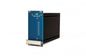
At the heart of the system is a Momentum PLC complete with processor, option adapter and I/O base. Additional digital I/O for monitoring of extra alarms is added as required up to a maximum of 8,192 drops, each capable of up to 32 I/Os. A Momentum PLC (and associated I/O) is interfaced to a number of touch-screen displays. A 10.4” screen is used for the maintenance display and a number of 5.7” touch-screens are used for the ATC equipment status displays.
Features
- Designed using state-of-the-art process control equipment.
- Design inspired by safety-first approach, including redundant elements, which can include power supplies and communications paths.
- Modular construction makes the system suitable for any airfield, of any complexity or particular needs.
- Adaptable to changes in an airfield’s physical layout without costly re-engineering.
- Touch-screen technology for maximum flexibility of operation and ease of change in response to changes in airfield layout.
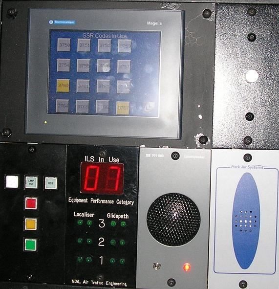
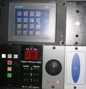
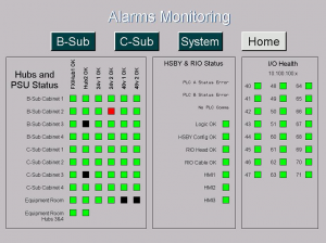
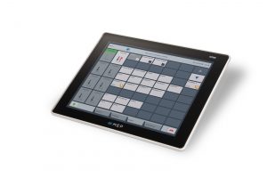
Maintenance Display
The Maintenance Display provides an “at a glance” view of the monitored equipment. The screen is split into two sections:
The top half of the screen to the left of the yellow “Equipment Status” bar provides an alarm overview with buttons to enable further pages to be selected or to give a more ‘in depth’ look at the systems.
The bottom half of the screen to the right of the “Equipment Status” bar is purely a status area giving information on equipment, airfield and emergency status.
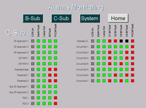
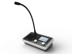
ATC Status Display
Status displays can be connected wherever they are needed. They are connected either by a Modbus Plus multi-drop cable network or by a direct line using Modbus (RS232) connectivity.
Airfield and Emergency Status
One user panel can be designated as an Airfield Emergency Status Control Panel. This enables the user to change the Low Visibilty Procedure (LVP) category and the Emergency category as shown above. On entering the page, the four boxes on the left are ‘greyed out’. The user simply presses the select button and then the appropriate status button.
Once the status has been set the select button must be pressed again before each status change. This prevents accidental status change. The status change will be indicated to other users by the amber button on the main page of their displays changing to red.
The user then simply presses the status button and then enters the status.
Other Products From Copperchase

ATIS and D-ATIS - Automatic Terminal Information Service

Digital Voice Communications System
Line Communications Equipment
Four Radio Control Panel