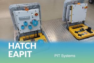
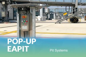
Underground Hatch PIT System
| Company | ElectroAir |
|---|---|
| Product code | EAPIT series |
Images

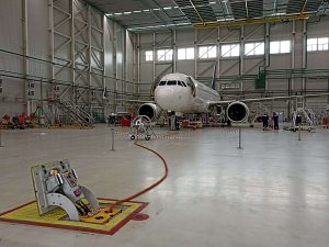

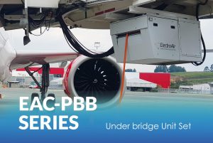
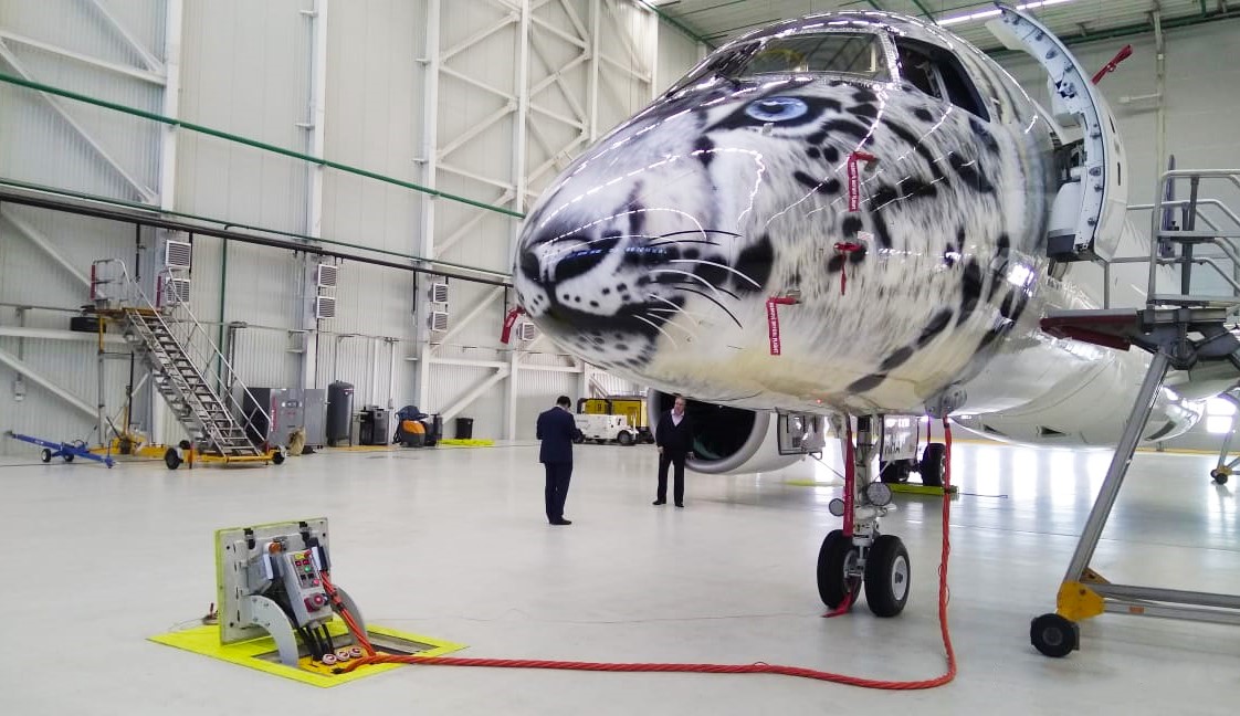
Underground hatch PIT systems are counterweight systems that are designed to supply power to onboard electrical equipment of aircraft and helicopters during pre-flight preparation at airports, shop floors of aircraft industry enterprises, or a hangars.
There are plugs on the upper part of the hatch to supply the aircraft with special current of either 400 Hz AC or 28.5 VDC.
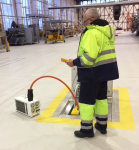
EAPIT can be equipped with a remote control and access system. On the lower part, there is a distribution box with a set of sockets. EAPIT is assembled as much as possible to simplify its installation and connection.
It is strongly recommended using ElectroAir GPUs with ElectroAir hatch PIT systems. By using them as a complete solution, it is possible to install GPUs far from the location of the PIT system.
If needed systems of compressed air and water (potable, blue, sewer) can be also built in to the PIT system. In addition, ElectroAir provides PCA and facility PIT systems. The PCA PIT system is equipped with a PCA rigid hose.
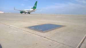
Underground chamber design is protected against foreign objects, dirt, rain and ground water ingress through the lid hatch. The corrugated outer surface of the cover eliminates slippage of an aircraft chassis, wheels of trucks and other vehicles. The cover is protected from spark formation due to collisions with metal objects. The cover holds up to 90t (according to EN 124 F900).
EAPIT can be installed into concrete chamber or chamber made of metal. Concrete chamber shall be produced by the customer according to ElectroAir recommendations.
General Parameters
|
Documentation
Optional
|
Input parameters
Output parameters
|
|
Control panel
|
Protection
|
Other Products From ElectroAir

Mobile Hybrid EA-ACU Series Air Conditioner Unit

Battery Driven GPU – APA-ECO SERIES

Diesel APA-10 Rectifier